
- Home
- >
- Products
- >
- Glass Insulator
- >
Glass Insulator


- Information
- Product Description
- Video
- Download
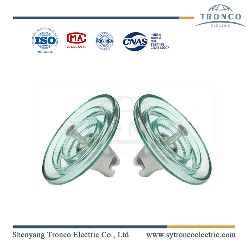
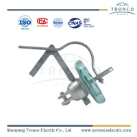
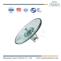
Glass Disc Insulator Introduction
Toughened glass insulators are used in overhead lines, with mechanical failing load 40kN-300kN. The end fittings are cap & pin, or tongue & clevis. Insulation part is toughened glass. There are standard type and fog type (heavy pollution area).
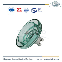
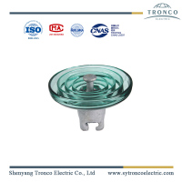
1. Insulator Structure:
The glass disc insulator consists of Cap and Pin, a Glass part, a Locking device, and cement.
Materials of components:
Cap and pin: Hot dip galvanized Ductile iron and Forged steel, HDG.
Glass part: Toughened glass.
Locking device (split pin): Stainless steel, R clip, or W clip.
Cement: Aluminate cement.

A cast-iron cap toughened glass part, and stainless steel pin agglutinated by cement into an integrated piece. A cylindrical head has been adopted for insulators, the most advanced structure in the world. The toughened glass insulators are free from defects and blemishes that may adversely affect the life of the insulator. All exposed glass parts have a smooth surface. All parts are interchangeable for easy replacement during maintenance.
Galvanizing: All ferrous line fittings shall be effectively galvanized.
Galvanizing shall be applied by the hot dipped process generally in accordance with BS 729 or ISO 1461 for iron and steel hardware.
For structural steel, galvanizing shall average not less than 85μm.
All steel bolts are hot dip galvanized including the threaded portions. All associated nuts shall be galvanized with the exception of the threads, which shall be oiled.
The zinc coating is smooth, clean, of uniform thickness, and free from defects. The preparation for galvanizing and the galvanizing itself shall not adversely affect the mechanical properties of the coated material.
2. Technical Specifications:
IEC Type Model | U70B | U70BP | U120B | U120BP | U160B | U160BP |
Diameter D( mm ) | 255 | 280 | 255 | 280 | 280 | 280 |
Spacing H( mm ) | 146 | 146 | 146 | 146 | 170 | 170 |
Creepage distance L( mm ) | 320 | 450 | 320 | 450 | 400 | 450 |
Socket coupling( mm ) | 16 | 16 | 16 | 16 | 20 | 20 |
Mechanical failing load( mm ) | 70 | 70 | 120 | 120 | 160 | 160 |
Mechanical routine test( kN ) | 35 | 35 | 60 | 60 | 80 | 80 |
Wet power frequency withstand voltage(kV) | 40 | 50 | 40 | 50 | 45 | 50 |
Dry lightning impulse withstand voltage(kV) | 100 | 125 | 100 | 125 | 110 | 125 |
Impulse puncture voltage( P.U ) | 2.8 | 2.8 | 2.8 | 2.8 | 2.8 | 2.8 |
Power frequency puncture voltage( kV )130 | 130 | 130 | 130 | 130 | 130 | 130 |
RIV( µV ) | 50 | 50 | 50 | 50 | 50 | 50 |
Corona visual test( kV ) | 18/22 | 18/22 | 18/22 | 18/22 | 18/22 | 18/22 |
Power frequency electric arc voltage | 0.12s/20kA | 0.12s/20kA | 0.12s/20kA | 0.12s/20kA | 0.12s/20kA | 0.12s/20kA |
Net weight per unit( kg ) | 3.6 | 5.8 | 4 | 5.8 | 6.7 | 7.2 |
3. Manufacture Process
| TECHNICAL FLOW CHART FOR MANUFACTURING PROCESS OF GLASS INSULATOR | |||||||
|---|---|---|---|---|---|---|---|
| Raw materials | Incoming inspection | Material mixed | Melting | Shaping | Annealing | Filtering | Toughening |
| Metal fittings | |||||||
| Cold shock | Visual examination | Cold & hot | Visual examination | Cold & hot shock | |||
| Visual examination | Cold & hot shock | Visual examination | Firing | Homogeneous furnace processing | |||
| Visual examination | Semi-finished storage | Visual examination | Assembly | Steam maintenance | |||
| Routine test | Finished product inspection | Sample test | Packing | Storage | |||

4. Glass Insulator Test Standard
Unless otherwise specified, the specifications for cap and pin glass disc insulators include but are not limited to the following standards as reference.
IEC 60383-1 (1993-04)
BS EN ISO 1461
BS 3288: Part 1:1997
IEC 60305: 1995 4th Ed.
Routine and sample tests can be carry out in our factory according to IEC or ANSI. Sample test items are as below
Visual inspection
Verification of the dimensions
Verification of locking system
Galvanizing test
Lightning impulse withstand voltage test.
Mechanical failing load test.

5. Packing and shipment
The glass pole line insulator by strings is packed with plywood crates that are free from fumigation on pallets. The insulators are loaded in the containers by forklift.

6. Advantages of glass insulator
Zero spontaneous breakage and easy inspection.
Excellent arc-resistance and vibration-proof performance.
Good self-cleaning and least aging.
Large electric capacitance, homogenous distribution of voltage on single string insulators.
7. Application
Glass insulators are applied in HV and MV transmission lines as dielectric and use for suspending conductors.

Mechanical failing load range: 40kN~300kN for both standard type and fog type.
Line voltage: 10kV~500kV.


