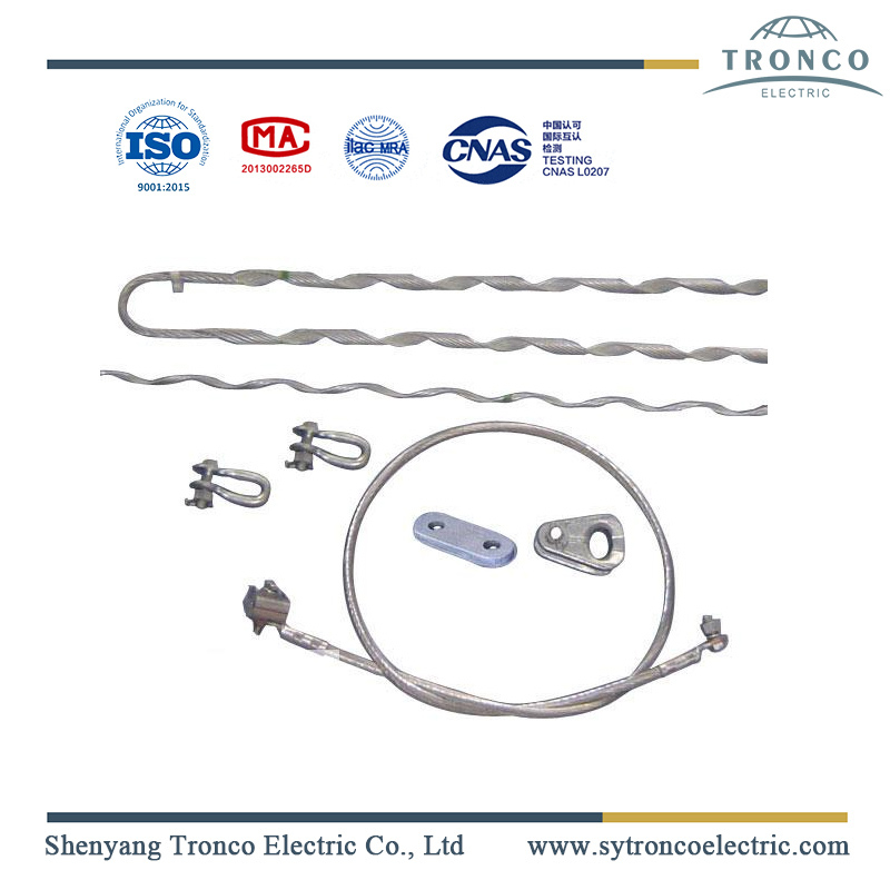
OPGW Tension Assembly
- Information
- Product Description
OPGW Tension Assembly Introduction
Dead-end support assembly can withstand without permanent deformation on any of the components, a conductor tension equal to the full rated ultimate strength of the conductor applied
simultaneously on the sub-conductors in a bundle. Sufficient articulation is provided such that the complete assembly including the insulator units can be attached in the vertical position and then moved to the horizontal position.
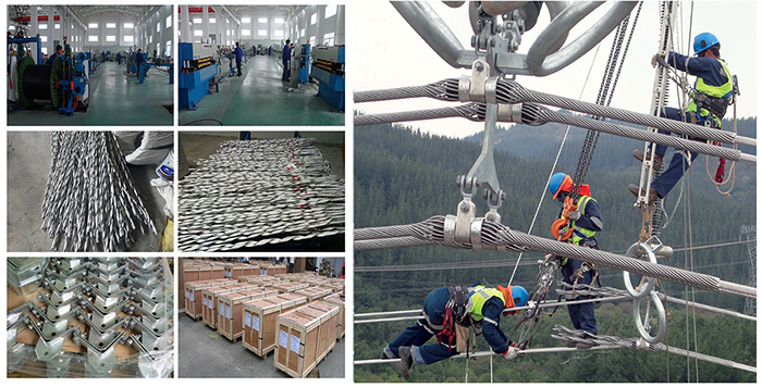
Provision is made on both sides of each string for the attachment of a strain carrier to facilitate the replacement of insulator strings for all types of assemblies during hotline maintenance. OPGW tension clamp assembly is designed in such a way that the load will be evenly distributed in the bundle strings at all times. The OPGW tension assembly can develop 95% of the full rated strength of the OPGW and under this condition, no lippage can occur.
Installation of Hardware and Accessories of OPGW
Install the fittings and accessories in 48 hours after tightening the cables in the tension section to avoid unnecessary damage to the fibers caused by overfatigue of the cable, for the cable could be easily
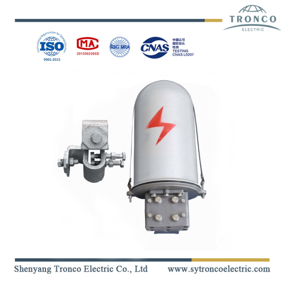
abraded or vibrates in the pulley. Fittings and accessories of OPGW usually include tension clamp, suspension clamp, special earth wire, vibration damper, armor rods, downlead clamp, joint box, and so on.
Installation of tension clamp
Tension clamp is the key hardware to install OPGW which not only fixes the cable on the pole and tower
and affords much pressure but also grips the cable tightly while not exceeding the side pressure intensity
of OPGW. Tension clamp is usually used in the termination tower, corner tower of over 15°, cabling tower, or pole tower of large altitude difference. The standard pre-stranding tension clamp is constituted of inner stranding wire, outer stranding wire, thimble, bolt, nut, and so on.
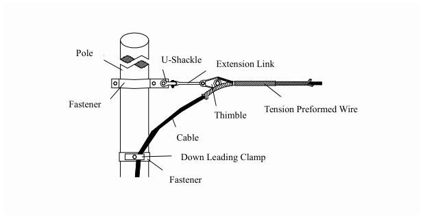
Steps of installation:
Fix the hardware in the tower after the cable arc is adjusted with putt-off equipment.
Pull the outside stranding wire of tension set through the heart-shaped loop of the transit hardware. Make the stranding wire parallel with the cable and mark the cable in the place of the coloring on the wire.
Correspond the inside stranding wire with mark on the cable, and then, reel the first group of pre-stranding wire on the cable. Reel the other pre-stranding wires or insert the grounding flake by the coloring mark to ensure all the pre-stranding wires reeling together tightly and the ends are trim and well-proportioned. Prevent pre-stranding wire from transmutation by overexerting so as not to influence the distance of bolts.
Put the pre-stranding wire into the thimble and correspond the cross-section mark of the outside stranding wire with the coloring earmark of the inside stranding wire. And then, reel the outside stranding wire. Keep the space symmetrical no matter reel from one part or two parts.
The OPGW tension assembly consists of a spiral tensioner fixed to the tower through a heart-shaped thimble, an extension piece, and shackles. The joint between the cable and tower is shunted by an aluminum alloy and is of sufficient length to distribute a low radial pressure uniformly over the OPGW. The tension assemblies are capable of resisting a load equal to 95% of the tensile strength of the OPGW.

